Using Encircled Flux Compliant Light Sources For Testing Fibre Optic
October 12, 2016
 International standards development organizations including ISO/IEC and ANSI/TIA are updating several key standards documents that affect field-testing of fibre optic cabling. In particular the
standards now describe the use of encircled flux compliant light sources.
Encircled flux refers to the distribution of light exiting the launch fibre of a light source used for testing. An ideal launch condition is one where light intensity is an even radial pattern across the face of the launch fibre. The purpose of the standards is to ensure that different test systems from any manufacturer report the same loss for a given cable under test.
Variation in LED and VCSEL launch patterns means that the optical power injected into the cable under test can result in variances in measured power loss values depending on connector alignment or the rotation of the launch cable. This is especially critical in multimode systems where the large fibre core will accept the uneven distribution from the light source and couple it into the cabling under test.
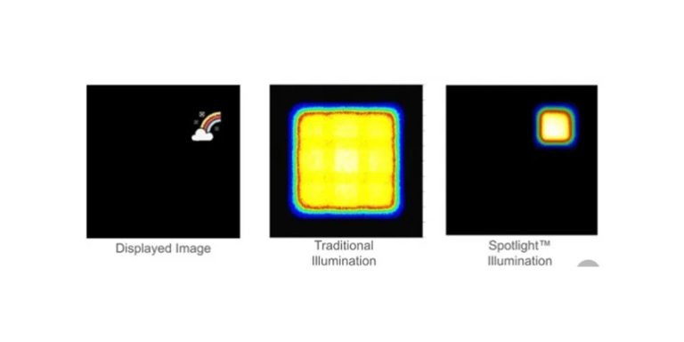
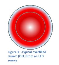 Figure 1 depicts the output from an LED into the launch fibre. While the light is distributed axially through the fibre, the intensity is much higher at the edge of the core (represented by a darker red colour) and a noticeable amount of power is present in the cladding (outer ring), creating an overfilled launch condition.
The results are artificially high loss readings when mandrels are not used on the launch cable or when there is mild misalignment between two connectors.
The reasons are that light in the cladding attenuates very quickly, and if this jumper were connected to the power meter during calibration, the light in the cladding will be detected, though it will dissipate in the cable under test and result in a high insertion loss measurement.
Additionally, when the core is overfilled, small misalignments between two connectors can result in abnormally high loss. Especially if the power distribution is weighted to the outside of the core as depicted in Figure 1.
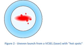
Figure 2 depicts the output from a VCSEL, which is a low cost laser used in multimode systems to provide higher bandwidth at longer distances. A VCSEL typically has an elongated output that creates a “blade” of light in the fibre core that maintains its shape as it propagates down the cable.
VCSELs also produce spots of high intensity light that further reduce the even distribution of power. In this diagram the spots appear to be dirt, but are actually intense modes (beams) of light.
Rather than try and control the output pattern of LEDs and VSCELs, the solution to the problem is to use specialized launch cables (in the past called mode conditioning cables) that accept an uneven light pattern, scramble it and emit an even light pattern.
These cables can be used with virtually any LED light source and make it encircled flux compliant. While these specialty cables are expensive, they have the benefit of allowing installers to keep their existing multimode light sources and make them encircled flux compliant by simply replacing the launch cable.
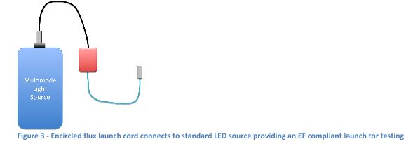
Figure 3 depicts an encircled flux launch cord connected to a light source. This cord replaces the standard launch cord when testing the installed cabling. The output from the EF launch cord into the fibre under test has an even distribution pattern that does not extend into the cladding of the fibre. Because the distribution pattern depends on whether the fibre core is 50 or 62.5 micron, the EF cord used for testing must match the core size of the fibre under test.
Multimode fibre optic systems do have limitations when compared to single-mode, but their key advantage is the lower cost of the active equipment in the system. And as multimode systems support data rates of 100Gb/s and more, the loss budgets become increasingly stringent.
Therefore, installers need to utilize every tool and technology available to ensure they obtain accurate test data and give themselves the best probability of a problem-free testing experience.
While the encircled flux testing requirements will slowly make its way into contracts and testing requirements, installers should not delay in ensuring the test cords that accompany their power meters and light sources are made with reference grade connectors.
One last note; even the best connectors, launch cables and testers are useless if the end faces are not kept perfectly clean. It’s critical that technicians apply best practices and clean the ports of the test equipment and test cords every time they are used.
When combined, reference-grade connectors/cords, encircled flux compliant launches and clean connectors will provide the best possible testing experience resulting in fewer failed tests and less time spent troubleshooting.
This article was first published online by Ideal Networks: www.idealnetworks.net/US/EN/News/Using-Encircled-Flux-Compliant-Light-Sources-for-Testing-Fiber-Optic.aspx.